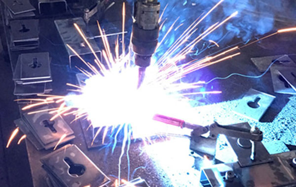
CO₂ Shielded Arc Welding, formally known as Carbon Dioxide Gas Shielded Arc Welding, is a process that utilizes CO₂ as the shielding gas to protect the weld pool from atmospheric contamination. It is widely applied in the welding of carbon steels and low-alloy steels.
1. Working Principle
- Under high temperature of the arc, CO₂decomposes into CO and O₂, forming a protective atmosphere that isolates the molten pool from nitrogen, hydrogen, and other harmful gases in the surrounding air.
- The welding wire serves both as the electrode and as the filler metal. It is continuously fed into the arc, where it melts and fuses with the base material to form the weld.
- The process typically employs direct current electrode positive (DCEP), where the wire is connected to the positive terminal. This setup ensures a stable arc and allows for deeper penetration.
2. Characteristics
Advantages:
High efficiency: Continuous wire feeding enables faster welding speeds compared to manual arc welding.
Cost-effective: CO₂ is inexpensive and readily available, making the process economically viable.
Versatility: Suitable for thin and medium-thickness materials; supports all-position welding (flat, horizontal, vertical, overhead); widely used in industrial applications.
Disadvantage:
The process tends to produce a relatively high amount of spatter, which may require post-weld cleaning or spatter control measures.
3. Equipment Configuration
- Welding power source: Typically a constant voltage or drooping characteristic power supply.
- Wire feeding unit: Feeds solid wire (commonly 0.8–1.2 mm in diameter) into the arc.
- Welding torch: Equipped with a gas nozzle and contact tip to direct gas flow and conduct current to the wire.
- Gas cylinder and pressure regulator: Supplies stable CO₂ shielding gas at a flow rate typically between 10–20 L/min.
- Control system: Allows precise adjustment of welding parameters such as current, voltage, and wire feed speed.
4. Operating Procedure
- Thoroughly clean the workpiece surface to remove oil, rust, and contaminants. Verify the purity of the shielding gas before welding.
- Adjust the torch-to-workpiece angle in accordance with welding position and joint configuration.
- Initiate gas flow approximately 2 seconds before arc striking, and properly fill the weld crater during arc termination.
- Minimize spatter by selecting appropriate wire types (e.g., flux-cored wire) or by using gas mixtures if applicable.
- Increase welding current and optimize travel speed to achieve full penetration as required by the welding specification.
- Fine-tune the torch angle and travel speed to ensure uniform bead appearance and sound weld formation.